Welcome to Dong guan Hecon Electronics Co., ltd official website


Blog
Connectors & Cable Assemblies Manufacturer
Strong and Steady DIN 41612 Connectors for Your PCB
Release time:
2025-07-18
Guide to Using DIN 41612 Connectors in PCB Assembly
Strong and Steady DIN 41612 Connectors for Your PCB
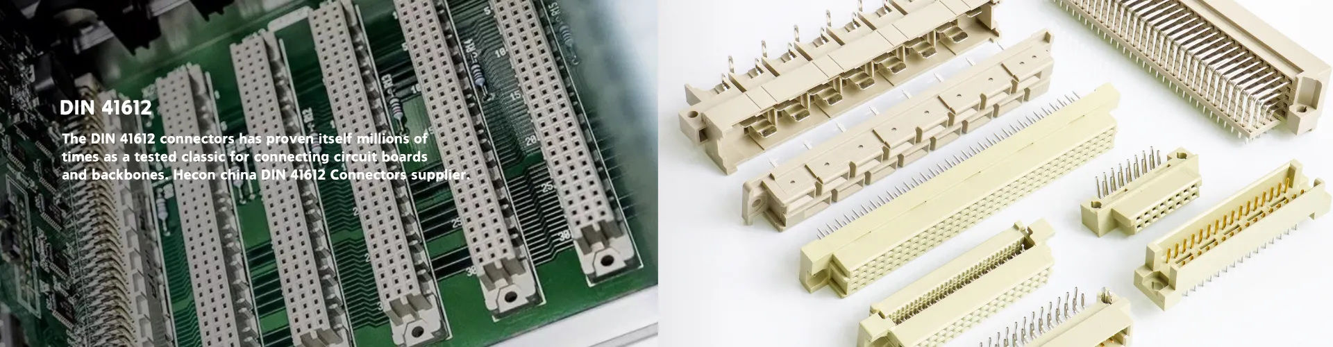
DIN 41612 Connectors give you a trusted way to link circuit boards in many electronic systems. You find these connectors in rack-based setups, where strong and steady connections matter.
1.You can pick from many types, with one, two, or three rows and up to 96 contacts.
2.They offer secure locking, prevent mismating, and handle high currents.
3.Their design stands up to shock, vibration, and tough environments. You can rely on DIN 41612 Connectors when you need lasting quality for your PCB designs.
Key Takeaways
DIN 41612 connectors make strong and steady links for modular electronic systems and PCBs. They come in many types and pin numbers, so you can pick what fits your design best. These connectors work well in hard places, like very hot or cold areas, and where there is shock, shaking, or wetness. Always look at the electrical ratings, mechanical details, and certifications like UL, CE, and RoHS before you pick a connector. Good PCB layout and using the right tools help make strong, long-lasting connections and stop common mistakes. Testing connectors for good signals and strength helps stop problems and keeps your system working well. Do not make mistakes like picking the wrong connector, making a bad layout, or ignoring the details, because it saves time and money. Using certified, high-quality DIN 41612 connectors from trusted sellers keeps things safe and working well for a long time.
DIN 41612 Connectors Overview
Definition
DIN 41612 connectors are board-to-board connectors made by the German Institute for Standardization (DIN). Many modular electronic systems use these connectors. The standard tells how they should look, how big they are, and how well they must work. DIN 41612 connectors have a rectangle shape with many pins in rows and columns. The space between each pin is 2.54 mm. These connectors are known all over the world and match IEC 60603-2 and EN 60603-2 standards. You can trust their steady quality and that they fit with many systems.
Note: DIN 41612 connectors are used in communication standards like the VME Bus. They are now a global standard for modular electronic connections.
Features
DIN 41612 connectors give you many helpful features:
Mechanical Strength: The connectors are made with strong materials. The housing uses PBT-UL94V-0. The contacts are made from phosphor bronze. Gold plating over nickel helps them conduct electricity well and keeps them from rusting.
Reliability: These connectors can be plugged in and out up to 250 times. They work in tough places, even from -55°C to 125°C.
Modularity: You can pick single, double, or triple row types. Standard pin counts, like 96 pins in three rows, help with complex designs.
Ease of Use: The IDC type, such as HECON’s 2.54mm Euro DIN41612 Female IDC Type 3rows 96P Connector, makes assembly and repairs easier. You can swap out broken parts fast and upgrade your system when needed.
Here is a quick look at the HECON 2.54mm Euro DIN41612 Female IDC Type 3rows 96P Connector:
| Feature | Specification |
|---|---|
| Pitch | 2.54 mm |
| Rows | 3 |
| Total Pins | 96 |
| Contact Material | Phosphor bronze, gold over nickel |
| Housing Material | PBT-UL94V-0 |
| Rated Current | 2.0 AMP |
| Voltage | Up to 500V AC/DC |
| Operating Temperature | -55°C to 125°C |
Applications
DIN 41612 connectors are used in many high-performance and modular systems. You will find them in:
1.Telecommunications equipment
2.Industrial control systems
3.Computing systems and servers
4.Test equipment and instrumentation
5.Embedded systems
These connectors are great for card-and-rack modular systems. You can use them to link PCBs with backplanes or other parts. The design lets you connect or disconnect modules without seeing the alignment. This makes fixing and upgrading much easier.
When you use the HECON 2.54mm Euro DIN41612 Female IDC Type 3rows 96P Connector, you make assembly and mass production simple. You can change out broken parts fast and upgrade old ones. This helps you add new technology and build systems that can change as needed.
Why Choose DIN 41612
Strength
You need connectors that work in hard places. DIN 41612 connectors are strong and last a long time. Makers test them by plugging and unplugging them many times. In one test, engineers did 10,000 plug-ins with a similar connector. The contact resistance stayed the same or got better. This happened because the contacts got smoother each time. The nickel under the gold did not show. This means the connector stayed tough and worked well. You can count on these connectors to last in your system.
DIN 41612 connectors use strong materials too. The housing is made from PBT-UL94V-0. This material does not melt or break easily. The contacts are made from phosphor bronze with gold on top. This keeps the connector working after many uses.
Reliability
You want connectors that work in many places. DIN 41612 connectors work in hot and cold spots. Some models work from -65°C to 125°C. They can handle up to 1000 VAC. They keep working after many plug-ins and pull-outs.
Tip: These connectors pass hard tests for wetness, shock, and shaking. You can use them where it is very wet or shaky. Engineers test them with:
2.Temperature changes from -65°C to +125°C for 500 times
3. Shocks up to 100G
4.Vibration up to 12 gRMS
You can trust DIN 41612 connectors to keep your circuits safe.
Versatility
You can use DIN 41612 connectors in many ways. They fit small test tools and big servers. You can pick from many pin numbers and row types. This helps you find the right connector for your job.
These connectors work with different mounting styles. You can use them for board-to-board, cable-to-board, or backplane links. The standard shape makes it easy to swap or upgrade parts. You save time when you build or fix things.
DIN 41612 connectors give you many choices and strong performance for your designs.
Types and Configurations


Connector Types
You can choose from several connector types when working with DIN 41612 standards. The most common types are labeled as A, B, and C. Each type has a different pin arrangement and row configuration. Type A connectors usually have two rows, while Type B and Type C often have three rows. These types help you match the connector to your system’s needs.
Some connectors include coding or keying options. These features prevent you from plugging the connector in the wrong way. You can find connectors with special notches or keys that only fit one direction. This design keeps your system safe and reduces mistakes during assembly.
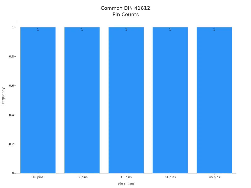
Pin Counts
You will see a range of pin counts in DIN 41612 connectors. The number of pins depends on the number of rows and the number of contacts per row. The most common configurations use one, two, or three rows. Each row can have 16 or 32 pins. This gives you popular pin counts like 16, 32, 48, 64, and 96 pins.
Here is a table showing some typical connector types and their pin configurations:
| Connector Type | Pin Configuration |
|---|---|
| B | 2 rows x 32 pins |
| C | 3 rows x 32 pins |
| R | 3 rows x 32 pins |
The 3-row, 96-pin configuration is a favorite for complex PCBs. You often find it in modular systems, test equipment, and bus-based systems like VME or PXI.
You can select the pin count that matches your circuit’s needs. For example, a 96-pin connector gives you high-density connections for advanced designs. Smaller pin counts work well for simpler or more compact systems.
Mounting Styles
You have two main mounting styles to choose from:
Vertical Mounting: This style lets you connect boards that stand upright. It works well when you want to stack PCBs or use backplanes.
Horizontal Mounting: This style allows you to connect boards that sit side by side. It helps when you have limited height or need to fit boards in a tight space.
Both mounting styles offer easy installation and maintenance. The standardized design ensures that you can swap connectors or upgrade your system without trouble. You also benefit from high-density connections and strong performance, even in tough environments.
Tip: Choose the mounting style that fits your PCB layout and available space. Both styles give you flexibility and reliability for many applications.
DIN 41612 Connectors Selection
Electrical Ratings
You need to check the electrical ratings before you choose a connector. These ratings tell you how much current and voltage the connector can handle. They also show the temperature range where the connector works best. If you pick the wrong ratings, your circuit may not work or could even get damaged.
Here is a table that shows the standard electrical ratings for DIN 41612 connectors:
| Parameter | Value |
|---|---|
| Current Rating (20°C) | 1.5 A |
| Maximum Current | 2 A |
| Test Voltage (rms) | 1000 V |
| Operating Temperature Range | -55°C to +125°C |
You should always match these ratings to your project. For example, if your circuit needs to carry 2 amps, make sure the connector supports it. If your device will be used in hot or cold places, check the temperature range. DIN 41612 Connectors give you strong performance in many conditions, so you can use them in tough environments.
Mechanical Needs:
1.You want your connector to last a long time. The materials used in the connector matter a lot. Look for connectors with housings made from PBT-UL94V-0. This material is strong and resists heat and fire. The contacts should be made from phosphor bronze and have gold plating over nickel. Gold plating helps the connector resist rust and keeps the connection stable.
2.You should also think about how many times you will plug and unplug the connector. Some connectors can handle up to 250 cycles or more. If you need to replace parts often, choose a connector with a high cycle rating. Good mechanical design means your connector will not break or wear out quickly.
3.Certifications help you know if the connector meets safety and quality standards. RoHS compliance means the connector does not use dangerous materials. This keeps your products safe for people and the environment. UL certification shows the connector has passed safety tests for electrical shock and fire. CE certification means the connector meets European safety and health rules. When you see these certifications, you know the connector is safe and reliable.
Tip: Always check for certifications like UL, CE, and RoHS. These marks show the connector meets strict safety and quality rules.
PCB Fit
1.You need to make sure the connector fits your printed circuit board (PCB). Check the pitch, which is the space between each pin. DIN 41612 connectors use a 2.54 mm pitch. This matches many standard PCBs. Count the number of rows and pins to see if the connector matches your board layout.
2.Think about how the connector will mount on your PCB. Some connectors mount vertically, while others mount horizontally. Choose the style that fits your design. Make sure the connector does not block other parts on your board.
3.You should also look at the size of the connector. If your board is small, pick a connector with fewer pins or a smaller body. For complex boards, a 96-pin connector gives you more connections in a small space.
Note: Always double-check the datasheet for the connector. This helps you avoid mistakes and makes sure the connector fits your board perfectly.
Environmental Factors
You need to think about where your connector will be used. Things like temperature, humidity, dust, and shaking can change how well it works. If you do not check these things, your system could break or need fixing sooner.
Temperature:
Look at the temperature range for your connector. Some connectors work from -55°C to 125°C. If your device is outside or near machines, you need a connector that handles hot and cold. Always pick a connector with the right temperature rating for your project.
Humidity and Moisture:
Water and wet air can make metal rust. Pick connectors with gold-plated contacts. Gold does not rust and keeps the connection strong. If your system is in a wet place, choose connectors that pass salt spray and humidity tests.
Vibration and Shock:
Machines and vehicles can shake or move a lot. Shaking can make connectors loose or break them. Choose connectors tested for vibration and shock. Some connectors pass tests with up to 100G shock and 12 gRMS vibration. This means they stay connected even when things move around.
Dust and Contaminants:
Dust can block the contacts and cause bad connections. Use connectors with tight housings. Some connectors have covers or seals to keep dust out. Clean connectors last longer and work better.
Tip: Always read the datasheet for test results. Look for certifications like UL, CE, and RoHS. These show the connector is safe and works well in tough places.
Here is a simple checklist to help you:
| Environmental Factor | What to Check | Why It Matters |
|---|---|---|
| Temperature | Operating range (-55°C to 125°C) | Stops overheating or freezing |
| Humidity | Gold plating, salt spray test | Stops rust |
| Vibration/Shock | Test ratings (G, gRMS) | Keeps connection tight |
| Dust | Sealed housing, covers | Stops bad connections |
You should always pick a connector that fits your environment. This helps your system last longer and work better.
Implementation Tips
PCB Layout
When you use DIN 41612 connectors, start with a good PCB layout. Place the connector footprint carefully on your board. Make sure the 2.54 mm pitch lines up with your PCB. Check that the connector does not block other parts or traces. Leave space around the connector so you can assemble and check it easily. Use clear silkscreen marks to show pin 1 and the direction. This helps you avoid mistakes when putting the board together. Keep signal traces short and straight. This lowers noise and makes signals better. If you use high-speed signals, put ground planes under the connector. This helps stop interference.
Tip: Always check the datasheet for the connector’s footprint and pad layout. This helps you avoid mistakes and saves time.
Soldering
Soldering DIN 41612 connectors is simple if you follow the right steps. Many connectors now work with thru-hole reflow (pin-in-paste) methods. This means you can solder them in the same oven as surface-mount parts. You save time and make fewer mistakes by using one process.
But you might have some soldering problems. Dendritic growth is one problem. Dendrites are tiny metal branches that can grow between pins. They can cause shorts and make your circuit stop working. High voltage, moisture, and leftover flux can make dendrites worse.
To stop these problems:
1.Keep your PCB and work area clean.
2.Clean off all flux after soldering.
3.Make sure solder joints are smooth with no sharp points.
4.Use solder that stops metal from moving.
5.Keep high voltages away from the connector, or add more space and insulation.
6.Protect your board from water and dirt with covers or coatings.
These steps help you make strong solder joints and stop future problems.
Assembly
Follow good steps during assembly so your DIN 41612 connectors work well. Makers say to use special IDC tools or crimping machines for wires. These tools help you make strong connections and do not hurt the wires.
Here is a table of important assembly steps and why they matter:
| Assembly Step | Description | Purpose |
|---|---|---|
| Use IDC or crimp tools | Use the right tool for wire termination | Makes sure contacts are strong and safe |
| Clean contacts | Take off dust and oils from contacts | Stops signal loss |
| Align wires properly | Put wires straight before pressing into slots | Lowers stress and helps good contact |
| Continuity and resistance test | Check for open/short circuits and low resistance | Checks if the connection is good |
| Hipot and pull testing | Test insulation and how strong the connection is | Makes sure it is safe and lasts |
| Regular inspection | Look for loose wires or worn contacts | Stops failures before they happen |
Always follow rules like IEC and DIN. These rules help your connectors work with other gear and keep your system safe. Check and fix your system often to catch problems early and keep it working well.
Note: Picking the right way to connect wires is important. IDC is quick and works well for most jobs. Crimping is stronger for hard jobs. Choose the way that fits your needs.
Testing
Testing your DIN 41612 connectors is a key step before you use them in your project. You want to make sure every connection works well and stays strong over time. Good testing helps you catch problems early and keeps your system running smoothly.
You can follow these main steps to check the integrity and performance of your connectors:
1.Crosstalk Analysis
You measure crosstalk to see if signals from one channel interfere with another. You check both near-end (NEXT) and far-end (FEXT) crosstalk. Low crosstalk means your signals stay clear and your data stays safe.
2.Vector Network Analyzer (VNA) Measurements
You use a VNA to check how signals move through the connector. This tool measures things like insertion loss (how much signal is lost), return loss (how much signal bounces back), and noise. These tests help you know if your connector keeps signals strong and clean.
3.Geometrical Optimization
You look at the shape and size of the connector and cables. You make sure the design fits well and does not cause extra noise or signal loss. Good geometry helps your connector work better and last longer.
4.Impedance Measurement with Time Domain Reflectometry (TDR)
You use TDR to check if the connector matches the right impedance. This test sends a signal and looks for reflections. If you see a big reflection, something is wrong. Matching impedance keeps your signals from getting distorted.
5.De-embedding Techniques
You remove the effects of test tools and adapters from your results. This step gives you a true picture of how the connector works by itself. You follow standards like IEEE 370-2020 to make sure your data is correct.
6.SerDes Simulation
You run simulations to see how well the connector handles fast data. You use eye diagrams to check if the signals are clear and open. This test shows if your connector can support high-speed data without errors.
Tip: Always test your connectors after assembly. Even small mistakes can cause big problems later.
You can use these tests to make sure your DIN 41612 connectors meet your needs. Careful testing helps you avoid signal loss, data errors, and system failures. When you follow these steps, you build stronger and more reliable electronic systems.
Common Mistakes
Wrong Selection
You might think all DIN 41612 connectors work the same way. This is not true. If you pick the wrong connector, your project can fail. You need to match the connector type, pin count, and mounting style to your PCB and system. Some engineers choose a connector just because it looks right or fits the board. This can cause problems later.
Common selection mistakes include:
1. Choosing the wrong number of pins for your signals
2.Picking a connector that does not fit your board layout
3.Ignoring the current or voltage ratings
4.Forgetting about the operating temperature range
Tip: Always check the datasheet before you order. Make sure the connector matches your electrical and mechanical needs.
If you use a connector with too few pins, you cannot connect all your signals. If you use one with the wrong mounting style, it may not fit your case. You should also check if the connector meets safety standards like UL or RoHS. This helps you avoid legal or safety issues.
Layout Errors
You need to plan your PCB layout carefully when you use DIN 41612 connectors. Many people make mistakes with the footprint or pin alignment. If you place the connector too close to other parts, you may not have enough space to solder or test it.
Watch out for these layout errors:
1.Misaligned connector footprints
2.Not enough clearance for assembly tools
3.Traces that cross under the connector and cause shorts
4.Forgetting to mark pin 1 or the orientation on the silkscreen
A good layout helps you avoid signal loss and makes assembly easier. You should use the recommended footprint from the connector’s datasheet. Double-check the pinout before you send your board for production.
| Layout Error | What Can Happen |
|---|---|
| Misaligned footprint | Connector will not fit |
| No clearance | Hard to solder or inspect |
| Poor trace routing | Signal loss or shorts |
| Missing silkscreen marks | Assembly mistakes |
Note: Always print out your PCB layout at 1:1 scale. Place the connector on the paper to check the fit before you order the board.
Poor Assembly
Even if you pick the right connector and design a good layout, poor assembly can ruin your project. You need to use the right tools and follow the correct steps. If you rush or skip steps, you can damage the connector or make weak connections.
Signs of poor assembly:
1.Bent or broken pins
2.Loose wires in IDC connectors
3.Cold or cracked solder joints
4.Dirt or oil on contact surfaces
You should use the correct IDC or crimp tools for wire termination. Clean the contacts before assembly. Check each connection with a continuity tester. If you see any problems, fix them before you power up your system.
Alert: Never force a connector into place. If it does not fit easily, stop and check your alignment. Forcing can break pins or damage the housing.
Good assembly keeps your system strong and reliable. Take your time and follow best practices for every step.
Ignoring Specs:
Some people skip reading the manufacturer’s specs for DIN 41612 connectors. This is a mistake that can cause big trouble in your project. Every connector has specs that show how to use it safely and how long it will last. If you do not follow these details, your circuit can get damaged. Your system may stop working right.
Manufacturers make DIN 41612 connectors with special materials and coatings. The contact plating keeps resistance low and the connection strong. If you use the connector more times than allowed, the plating wears out. This makes plugging and unplugging harder. You might feel it takes more force to connect. Sometimes, the connection works and sometimes it does not. These problems are hard to spot and fix.
Tip: Always check the number of mating cycles in the datasheet. If you go over this number, the connector might fail without warning.
Ignoring specs can make your circuit act strange. Your system might work during tests but fail later. This happens when the connector stops making a good connection. Engineers have seen this in real projects. Plugging and unplugging too many times caused hidden faults. The team fixed it by plugging and unplugging less often.
Here are some specs you should always check:
| Specification | Why It Matters |
|---|---|
| Mating Cycles | Stops worn contacts and bad signals |
| Contact Plating | Keeps resistance low and stops rust |
| Rated Current/Voltage | Stops overheating and damage |
| Operating Temperature | Makes sure it works in all climates |
Always use the connector within its limits. If you push it too far, your system can break. You might spend more time and money fixing problems.
1.Read the datasheet before you design your board.
2. Make sure your use matches the connector’s ratings.
3. Plan your work to avoid extra plugging and unplugging.
Alert: Connectors only work well if you use them as the maker says. Ignoring specs can make your strong design weak.
If you follow the specs, your PCB designs will be stronger and more reliable. You will save time, money, and avoid frustration.
When you pick DIN 41612 Connectors for your PCB, you get lots of good things. These connectors work well with many systems and are very reliable. You can use them in both simple and complex setups. They let you choose how much current you need, how many contacts you want, and how to mount them. They also have smart safety parts like coding, board locks, and pre-mating contacts to help keep things safe.
| Why Pick Certified Connectors? | What You Get |
|---|---|
| Standardization | Easy to use and keeps your system safe |
| Durability | Works well for a long time, even in hard places |
| Supplier Quality | You get trusted brands like HECON |
Use the tips in this guide when picking and putting together your connectors. This will help you make sure every connection is strong and works well.
FAQ:
1.What is a DIN 41612 connector?
A DIN 41612 connector links printed circuit boards in modular systems. It follows strict rules for size, pin layout, and how it works. You see it in many industrial and communication devices.
2.How do I choose the right DIN 41612 connector?
First, check what your system needs. Look at how many pins you need, the mounting style, current rating, and temperature range. Always match the connector’s specs to your project. Read the datasheet before you buy.
3.Can I use DIN 41612 connectors for high-vibration environments?
Yes, you can use them in places with lots of shock and vibration. The strong housing and tight contacts help your system stay connected, even when things get rough.
4.What tools do I need for assembly?
You need IDC tools or crimping machines to attach wires. Use a tester to check if the connections work. Clean the contacts before you start. These steps help you make safe and strong connections.
5.Are DIN 41612 connectors safe for high current?
DIN 41612 connectors can handle up to 2.0 amps, depending on the model. Always check the rated current in the datasheet. Never go over the connector’s limit to keep your system safe.
6.How do I prevent mismating during installation?
Use connectors with coding or keying features. These features help you plug the connector in the right way. This stops mistakes and keeps your system safe from damage.
7.What certifications should I look for?
Look for UL, CE, and RoHS certifications. These marks show the connector is safe, good quality, and meets environmental rules. Certified connectors help you build safe and reliable products.
8.Can I get custom DIN 41612 connectors?
Yes, you can get custom options from many suppliers, like HECON. You can pick the pin count, cable assembly, and packaging you want. You can also ask for samples or special features for your project.


Service Hot Line
Mobile:+86-180-0286-9136
E-mail:sales@dghecon.com
Website:www.dghecon.com
Address: 5th Floor, Building 1, No. 256, Shuixin Road, Dalang Town, Dongguan City, Guangdong Province